


|
The EB111 is a Mercury System expansion board with two Mercury System Sockets. The board allows to connect Mercury System BB with SBs, PBs and BLs in planar configuration. |
|||||||||||||
| Hardware Highlight | |||||||||||||
 |
|||||||||||||
|
|||||||||||||
| Block diagram | |||||||||||||
 |
|||||||||||||
| The Mercury System | |||||||||||||
|
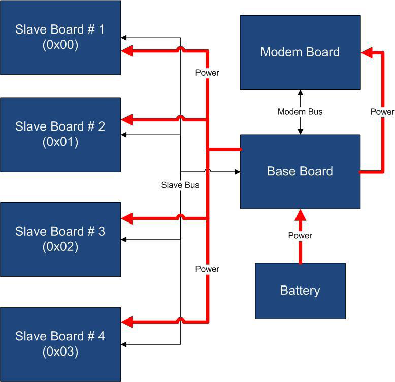
The Mercury System (MS in short) is a modular system for the development of connectivity and IoT applications. The system uses various type of electronic boards (logic unit, modems, slave boards equipped with sensors and actuators, power boards...) and a complete SW framework to allow the realization of complex applications. Scalability, ease of use and modularity are key factors and are allowed by the use of a heterogeneous set of components that allow to assemble the system like a construction made with LEGO© bricks. The board set which composes the system is made up by the following “families”:
Slave Boards and Modem Board are provided pre-programmed with a FW which implements a dedicated command set for a high-level management of the board, while the Base Boards are provided with a SW framework which encapsulates all the low-level services (operative system, device drivers, system services, etc.), leaving to the user the development of application level logic only. Moreover, the Base Board comes with an USB bootloader, so it can be programmed without the need of an external programmer. |
|||||||||||||
| Typical System Connection | |||||||||||||
 |
|||||||||||||
| Mercury System Framework | |||||||||||||
|
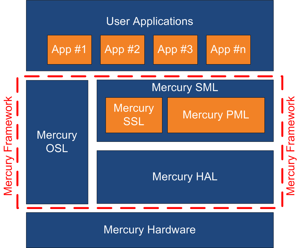
The Mercury System Framework (MSF) is a layered SW framework specifically designed to support application development with Mercury System. It provides to the user a complete set of base functionalities to easily interface MS Slave Boards (SB) and Modem Boards (MB) as well as some infrastructural and system services. Figure 12 shows the layered Architecture of the MSF. |
|||||||||||||
| Mercury System Framework Architecture | |||||||||||||
 |
|||||||||||||
|
The framework is made up by the following components: It’s divided in two main components:
OSL (Operative System Layer): this layer is made up by a lightweight RTOS that provides basic services to the system, like scheduling tables for the various tasks, Events, SW Timers, Alarms, etc… |
|||||||||||||
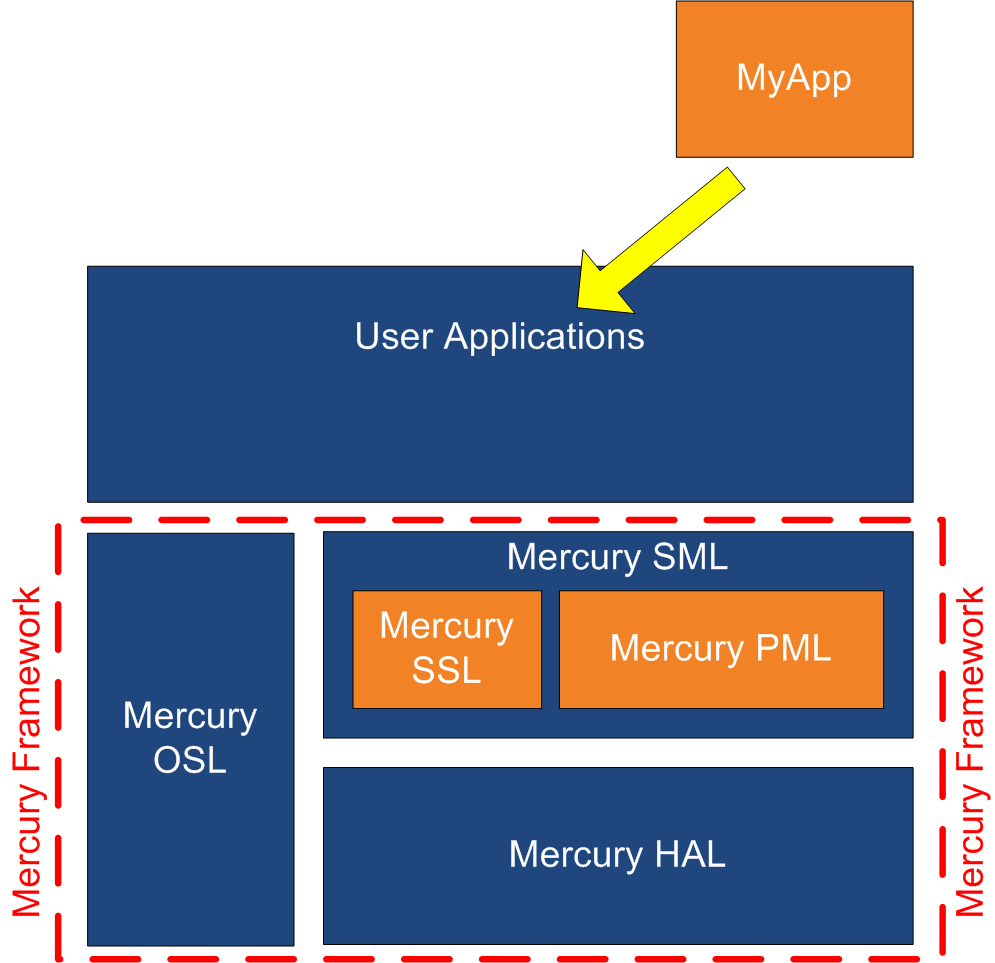
| Example of user application positioning inside the MSF | |||||||||||||
 |
|||||||||||||
| The Slave Boards | |||||||||||||
|
In order to develop applications, the Mercury System provides several different Slave Board, each of them containing a specific peripheral (could be a particular sensor, an actuator, a communication device, etc.), managed by a local controller. There are several sub-families of Slave Boards:
The following table provides some examples for each sub-family:
|
|||||||||||||
| Download | |||||||||||||

Mercury System MB210 – WiFi Modem Board
The MB210 is a WiFi Modem Board, able to add WiFi functionalities to a MS Base Boar..
Cod: 7305-MB210
Price: 9.00€

Mercury System EB210 – LCD 16x2 Expansion Board
The EB210 is a Mercury System expansion board with integrated alphanumeric 16x2 dis..
Cod: 7305-EB210
Price: 17.00€

Mercury System SB120 – Neopixel Slave Board
The SB120 is a 3-channel Neopixel board, able to interface Neopixel LEDs strips or ..
Cod: 7305-SB120
Price: 10.50€

Mercury System SB130 – Servo Slave Board
The SB130 is a 6-channel Servo board, able to generate and maintain an R/C servo co..
Cod: 7305-SB130
Price: 11.80€

Mercury System SB140 – HSD Slave Board
The SB140 is a 4-channel HSD (High Side Driver) board, able to control load up to 1..
Cod: 7305-SB140
Price: 18.50€

Mercury System SB320 – Infrared Slave Board
The SB320 is a 2-channel Infrared Sensor Board, able to interface two GP2Y0D810Z0F ..
Cod: 7305-SB320
Price: 8.80€

Mercury System SB810 – Proto Board Model A
The SB810 is a Mercury System Slave Proto Board. This board allow the user to make ..
Cod: 7305-SB810
Price: 9.50€

Mercury System - MB810 Modem Board ProtoA
Small board for the Mercury system with a prototyping area and provision for mounti..
Cod: 7305-MB810
Price: 4.00€

Mercury System PB110 – Power Board
Power Board (PB) is a Mercury system board that provides you with the power managem..
Cod: 7305-PB110
Price: 12.50€
Mercury System – EB111 Expansion Board Quad
- Brand: Futura Group Srl
- Product Code: 7305-EB111
- Availability: In Stock
-
Price: 9.00€