|
The SB320 is a 2-channel Infrared Sensor Board, able to interface two GP2Y0D810Z0F infrared proximity sensors. The heart of the system is a PIC16F1825 8-bit RISC microcontroller, produced by Microchip Technology Inc. The SB320 is connected to a Mercury System Base Board by means of I2C bus. The address of the board could be dynamically set by means of a 4 positions dip switch, allowing up to 15 address values (address 0x00 is reserved for I2C general call broadcast addressing scheme). The infrared sensors can detect objects in the range 2-10 cm. Each channel provides a digital proximity indication: 1 means than an object has been detected in the sensor proximity range, 0 that the range is free.
|
| Board Characteristics |
- Board Type: Slave Board (SB)
- Supported Bus: I2C
- Addressing: Dip Switch 4
- Peripheral Description: Infrared Sensor Input GP2Y0D810Z0F
|
| Hardware Highlight |
| |
 |
|
- User LED: Board User LED, by default it’s configured as heartbeat LED (periodic pulses).
- IR Sensor Connectors: Connectors for GP2Y0D810ZOF Infrared Sensor.
- Mercury Connector: Mercury connector used to interface the board with the others MS boards.
- Address Dip Switch: Dip Switch to set the address of the board within the Mercury System.
- MCU: PIC16F1825 main controller.
- Programmer Connector: PicKit 3 Microchip Programmer/debugger connector. It is directly connected to the MCU debug port, in order to allow advanced debugging and programming features, if needed.
|
| MCU Charateristics |
- Program Memory Type: Flash
- Program Memory (KB): 14
- CPU Speed (MIPS): 8
- RAM Bytes: 1,024
- Data EEPROM (bytes): 256
- Digital Communication Peripherals: 1-UART, 1-A/E/USART, 1-SPI, 1-I2C1-MSSP(SPI/I2C)
- Capture/Compare/PWM Peripherals: 2 CCP, 2 ECCP
- Timers: 4 x 8-bit, 1 x 16-bit
- ADC: 12 ch, 10-bit
- Comparators: 2
- Temperature Range (C): -40 to 125
- Operating Voltage Range (V): 1.8 to 5.5
- Pin Count: 20
- XLP: Yes
|
| Block diagram |
| |
 |
| |
| The Mercury System |
|
The Mercury System (MS in short) is a modular system for the development of connectivity and IoT applications. The system uses various type of electronic boards (logic unit, modems, slave boards equipped with sensors and actuators, power boards...) and a complete SW framework to allow the realization of complex applications. Scalability, ease of use and modularity are key factors and are allowed by the use of a heterogeneous set of components that allow to assemble the system like a construction made with LEGO© bricks.
The board set which composes the system is made up by the following “families”:
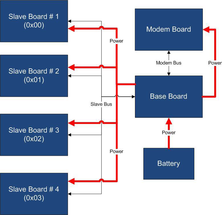
- Base Board (BB): It’s the “brain” of the system and contains the main logic unit as well as different communication buses and connectors to interfaces the slaves. It also contains a simple power supply system and a recharge unit for a single LiPo cell (it can satisfy the power requirements of simpler systems). It can exist in different variants, depending on the employed microcontroller unit.
- Modem Board (MB): it’s the board that allows network connectivity. It can exist in different variant, depending on the network interface (GSM/GPRS, Wi-Fi, BT, Radio…). It’s interfaced to the Base Board with a dedicated communication line.
- Power Board (PB): it’s the board that allows to satisfy the particular power requirements of the system, when it’s necessary. They can vary, depending on the particular power requirement to satisfy (high power, solar harvesting, piezo harvesting, etc.).
- Slave Board (SB): these are the system’s peripherals, and they vary depending on the specific mounted sensor or actuator. Typical examples are SBs with relays, temperature sensors, RGB LED controllers, servo controllers, accelerometers, etc. They communicate with the BB with I2C or UART channels and a dedicated command set.
- Expansion Board (EB): these are the boards that allow planar connection of Mercury System. There are variants which can contains Displays, battery socket, etc.
- Brain-Less Board (BL): these are the controller-less boards. They in general contain really simple sensors or actuators that don’t need the bus interface. There are meant as an alternative to slave boards for cost-sensitive applications.
Slave Boards and Modem Board are provided pre-programmed with a FW which implements a dedicated command set for a high-level management of the board, while the Base Boards are provided with a SW framework which encapsulates all the low-level services (operative system, device drivers, system services, etc.), leaving to the user the development of application level logic only. Moreover, the Base Board comes with an USB bootloader, so it can be programmed without the need of an external programmer.
|
| Typical System Connection |
| |
 |
| |
| Mercury System Framework |
|
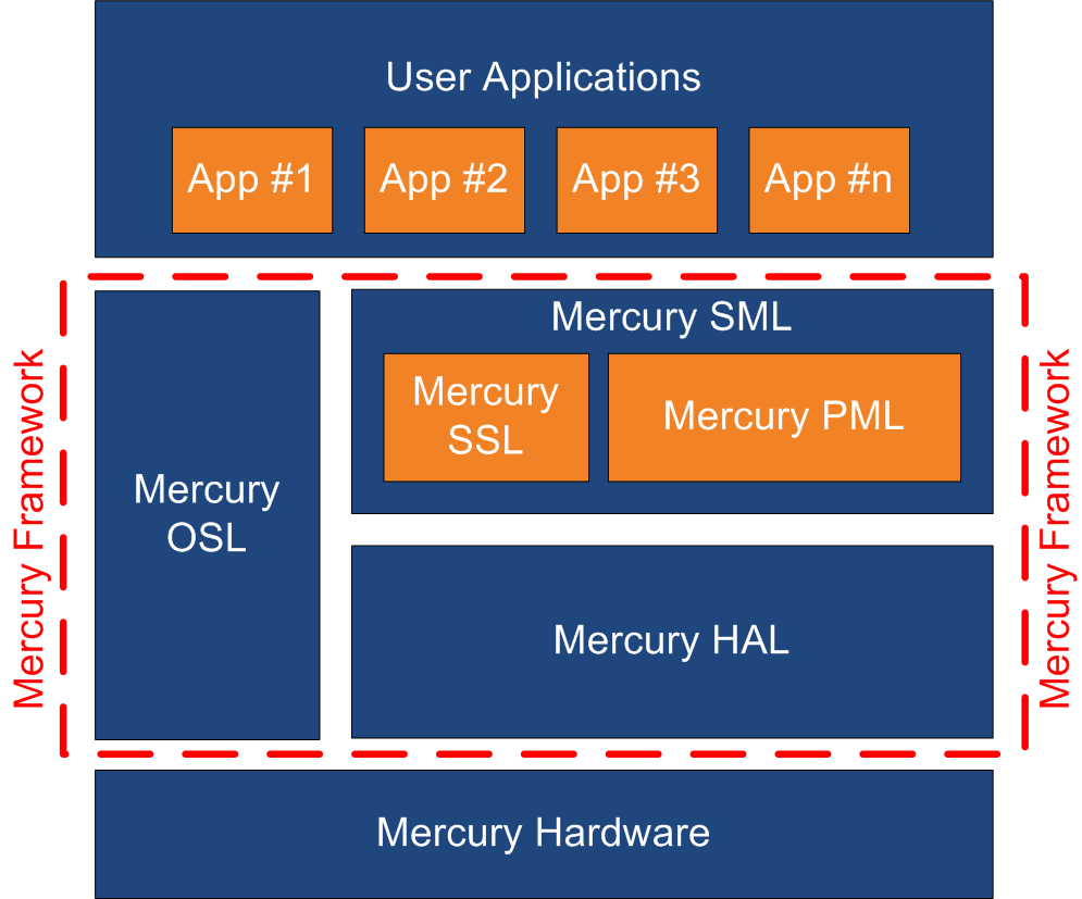
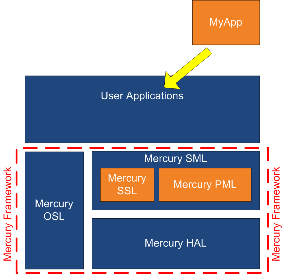
The Mercury System Framework (MSF) is a layered SW framework specifically designed to support application development with Mercury System. It provides to the user a complete set of base functionalities to easily interface MS Slave Boards (SB) and Modem Boards (MB) as well as some infrastructural and system services. Figure 12 shows the layered Architecture of the MSF.
|
| Mercury System Framework Architecture |
| |
 |
| |
|
The framework is made up by the following components:
HAL (Hardware Abstraction Layer): the purpose of this layer is to abstract the HW dependencies to the upper layers.
SML (System Management Layer): the purpose of this layer is to provide services for the management of communication buses (I2C, UART) and for the management of Mercury System’s Modem Board (WiFi, BT, GSM/GPRS). It also provides a set of System Services, like System Power Management, RTCC, USB terminal, etc.
It’s divided in two main components:
- PML: Peripheral Management Layer,
- SSL: System Services Layer.
OSL (Operative System Layer): this layer is made up by a lightweight RTOS that provides basic services to the system, like scheduling tables for the various tasks, Events, SW Timers, Alarms, etc…
|
| Example of user application positioning inside the MSF |
| |
 |
| |
| The Slave Boards |
| |
|
In order to develop applications, the Mercury System provides several different Slave Board, each of them containing a specific peripheral (could be a particular sensor, an actuator, a communication device, etc.), managed by a local controller.
The MS Slave Boards layout is standardized, in order to simplify the interfacing with the Base Board and ensure and high level of modularity and scalability. Each Slave Board is provided with a I2C (Inter Integrated Circuit) communication line and a four position dip-switch to dynamically set the bus address of the Slave Board. Addresses from 0x01 to 0x0F are available for the Slaves, while address 0x00 is reserved for broadcast communication. In this way up to 15 devices can be connected to the Base Board using the dynamic addressing scheme. This number can be even increased by reprogramming the Slave with a software provided address. Moreover, two open-collector digital lines connected to the Base Board external interrupts are provided for the Slave Boards that need to provide async interrupts. Moreover, slave Boards that need an higher bandwidth and peer-to-peer communication can be interfaced using an additional UART channel.
There are several sub-families of Slave Boards:
- Sensor SBs,
- Actuator SBs,
- Communication SBs,
- Interface SBs,
- Interface SBs
The following table provides some examples for each sub-family:
| Sub-Families |
Examples |
| Sensor SBs |
Ultrasonic, Infrared, Temperature&Humidity, PIR, Gas Sensor, Ari Quality, Thermocouple, Moisture, Analog Input, Accelerometer. |
| Actuator SBs |
Relè, High-Side Driver, Low-Side Driver, Servo, Motore DC, Stepper Motor, Neopixel |
| Communication SBs |
RS232, RS485, CAN, LIN, Ethernet, Bluetooth |
| Interface SBs |
Display OLED, Tastiera, Mini-Joystick |
| Interface SBs |
SD Card, decoder MP3 |
|
| |
| Download |
|
|


