


|
Add quadrature encoders to your micro metal gearmotors (extended back shaft version required) with this kit that uses a magnetic disc and hall effect sensors to provide 12 counts per revolution of the motor shaft. The sensors operate from 2.7 V to 18 V and provide digital outputs that can be connected directly to a microcontroller or other digital circuit. This module is compatible with all of the dual-shaft micro metal gearmotors we carry, including the HPCB versions. This kit includes two dual-channel Hall Effect sensor boards and two 6-pole magnetic discs that can be used to add quadrature encoding to two micro metal gearmotors with extended back shafts (motors are not included with this kit). The encoder board senses the rotation of the magnetic disc and provides a resolution of 12 counts per revolution of the motor shaft when counting both edges of both channels. To compute the counts per revolution of the gearbox output shaft, multiply the gear ratio by 12. |
|
 |
|
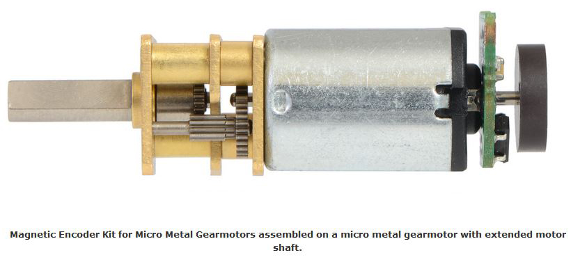
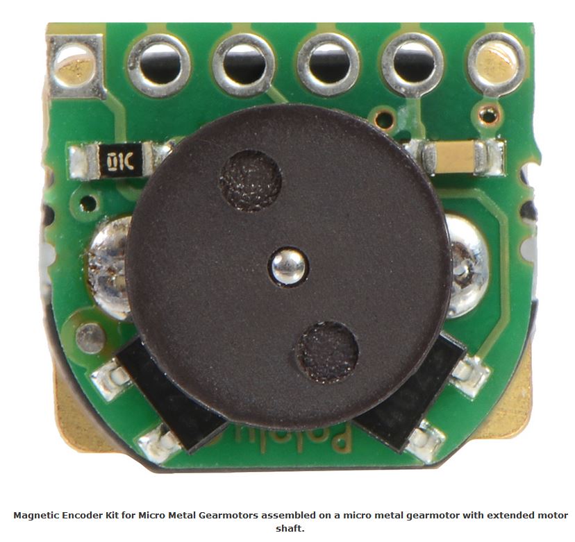
| Magnetic Encoder Kit for Micro Metal Gearmotors assembled on a micro metal gearmotor with extended motor shaft | |
| This compact encoder solution fits within the 12 mm × 10 mm cross section of the motors on three of the four sides, and it only extends 0.6 mm past the edge of the fourth side (note: if you need it to be flush with that last side, you can carefully grind the board down a little and solder to the remaining half-holes). The assembly does not extend past the end of the extended motor shaft, which protrudes 5 mm beyond the plastic end cap on the back of the motor.. | |
 |
 |
| Note: This sensor system is intended for users comfortable with the physical encoder installation. It only works with micro metal gearmotors that have extended back shafts. | |
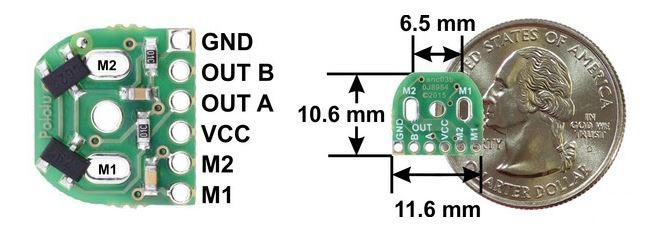
| Pinout & installation | |
| The encoder board is designed to be soldered directly to the back of the motor, with the back shaft of the motor protruding through the hole in the middle of the circuit board. One way to achieve good alignment between the board and the motor is to tack down the board to one motor pin and to solder the other pin only when the board is flat and well aligned. Be careful to avoid prolonged heating of the motor pins, which could deform the plastic end cap of the motor or the motor brushes. Once the board is soldered down to the two terminals, the motor leads are connected to the M1 and M2 pads along the edge of the board; the remaining four pads are used to power the sensors and access the two quadrature outputs: | |
 |
|
|
The sensors are powered through the VCC and GND pins. VCC can be 2.7 V to 18 V, and the quadrature outputs A and B are digital signals that are either driven low (0 V) by the sensors or pulled to VCC through 10 kΩ pull-up resistors, depending on the applied magnetic field. The sensors’ comparators have built-in hysteresis, which prevents spurious signals in cases where the motor stops near a transition point. |
|
 |
|
| Encoder A and B outputs of a magnetic encoder on a high-power (HP) micro metal gearmotor running at 6 V. | |
|
Technical Specifications
|
|
|
|
| Download | |

30:1 Micro Metal Gearmotor - 500 RPM
This small yet powerful motor is great solution for small robot operating at 6 Vdc with a reduction ..
Cod: 2846-MMG500
Price: 12.30€

298:1 Micro Metal Gearmotor HPCB 6V with Extended Motor Shaft
This gearmotor is a miniature high-power, 6 V brushed DC motor with long-life carbo..
Cod: 8218-EXTMMG298
Price: 28.00€
250:1 Micro Metal Gearmotor HPCB 6V with Extended Motor Shaft
This gearmotor is a miniature high-power, 6 V brushed DC motor with long-life carbo..
Cod: 8218-EXTMMG250
Price: 20.50€
Magnetic Encoder Pair Kit for Micro Metal Gearmotors, 12 CPR, 2.7-18V
- Brand: Futura Group Srl
- Product Code: 8218-ENCODERMAGN
- Availability: In Stock
-
Price: 8.80€
Tags: optical encoder, encoder pair, pair kit, cpr, wild thumber, motor shaft, encoder 6 Vdc, pololu