


 |
|
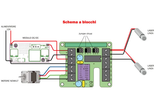
This is the shield used with Raspberry Pi to make a 3D scanner. In our blog, you can find all documentations. The driver allows to set the driveshaft’s direction of rotation and the number of degrees that the motor’s rotor has to do at the receiving of each command; in other words, we may decide if, when we give a command pulse, the module has to make the driveshaft rotate one step by one, or by 1/2, 1/4, 1/8, 1/16 or 1/32, depending on the desired accuracy. Actually, we set the functioning at a 1/32 of a step, by posing the pins MS1, MS2 and MS3 at the logical 1, so to obtain the greatest movement accuracy. Raspberry Pi commands the driver, by setting the logical state of the /STEP, EN and DIR lines; it sends the pulses that determine the advancement of a step at the time in the rotation of the driveshaft to the first one (managed via one among IO04, IO12 or IO25, freely chosen), while DIR (IO05, IO06 or IO18) is defined from time to time, depending on the fact you want to obtain a clockwise or counterclockwise rotation. EN (IO17, IO22 or IO27) is needed so to enable or disable the module. In order to command the rotation of a driveshaft’s step, the microcontroller poses EN at a high logical level and it keeps it in this condition, then it sets DIR at logical 1 if the rotation has to occur in counterclockwise direction or at logical zero for the clockwise direction (always keeping this logical condition as well) and finally it supplies a low level pulse to the /STEP line; once this has been done, it brings both EN and DIR to idle state. If the advancement has to be for more than one consecutive step, while EN and DIR are active the microcontroller sends the required pulse sequence to /STEP. Please remember that the motor moves, for each pulse that Raspberry Pi sends on /STEP, accordingly to the settings of MS1, MS2, MS3; in our case 32 of them are needed in order to make a step. Please notice that for each driver’s command line we have considered the possibility to choose – by means of bridges – among three GPIO lines; this has been done so to give you the possibility to mount more than one shield on Raspberry Pi 2 and thus to manage other applications, in addition to the scanner, and also to use the shield as general controller for other usages, and maybe to command two or three stepper motors (in that case it is almost inevitable to use different GPIOs for the various boards). Once the shield has been mounted, please place the jumpers as you please and write it down, since you will then have to set the GPIO lines in the software, accordingly to what will be explained later.
This being said, we will go on by claiming that each driver is composed of a double H-bridge, governed by an electronics that allows to set the electromagnetic field’s direction of rotation and therefore the one of the stepper motor’s driveshaft. Each time that a pulse comes on the STEP pin at a high level (the minimal tolerable duration is 1 µs) – unless there are different settings – the 1A, 1B, 2A and 2B outputs supply the pulses used in order to command if the motor’s rotor will move by a step or a fraction of it. We will end the overview concerning the drivers by talking about the /SLEEP pin, that activates the sleep mode (active logic and drivers turned off) and about RST, that resets the controller that governs the drivers and that sets the motor’s command outputs (1A, 1B, 2A, 2B) to a logical zero, even if STEP continues to receive pulses. In our application, RST and SLEEP are deactivated, since SLEEP has an internal pull-up resistor and by joining them they are both at 1. The shield is pre arranged in order to receive two distinct power sources: VMOT is applied to the specific terminal box (and it is the 12 volt DC one for the motor), while 5V (mentioned on Raspberry Pi’s expansion connector) powers the driver’s logic and the ULN2003 line-driver. This project comes in kit . Some components have to be soldered to the included PCB.
|


DC/DC Power Converter 1.5V ÷ 35V / 3A
DC / DC step down converter (48,35 x 23,35 x 14 mm), capable of converting a DC voltage between 3 ..
Cod: 2846-MODULODCDC
Price: 3.55€

Stepper motor NEMA17 - 1,8° - 2,5A
Bipolar stepper motor with a 4-wire cable used in 3Drag 3Dprinter Features: Step Angle (d..
Cod: 7300-STEPMOT3DRAG
Price: 20.00€

Raspberry Pi 3 Model B with Wi-Fi and Bluetooth
The Raspberry Pi Type B 3 is the third gen..
Cod: 7310-8968660RS
Price: 53.00€

5mW red laser module Line - 650nm
Laser module with the semiconductor diode and emission at 650 nanometers. It has an..
Cod: 2510-LASER5MWLINEA
Price: 12.00€

IR camera with 2 IR LED 3W for Raspberry Pi
Module for Raspberry Pi comes with camera sensitive to infrared radiation, sensor 1..
Cod: 2846-RASPBERRYCAMIR
Price: 29.00€

Raspberry Pi 3 Model B+
<!--cke_bookmark_155S--><!--cke_bookmark_155E--> ..
Cod: 7310-RPI3BPLUS
Price: 56.00€

Raspberry Pi 4 Model B 8GB
Raspberry Pi 4 Model B is the fourth generation produced by the Raspberry Foundatio..
Cod: 7310-RPI4-8GB
Price: 160.00€

Raspberry Pi 4 Model B 4GB
Raspberry Pi 4 Model B is the fourth generation produced by the Raspberry Foundatio..
Cod: 7310-RPI4-4GB
Price: 110.00€
Raspberry Pi shield for 3D Scanner
- Brand: Futura Group Srl
- Product Code: 7100-FT1255K
- Availability: In Stock
-
Price: 17.50€
Tags: Raspberry Pi, shield, 3D Scanner