


|
Breakout board based on the D7S produced by Omron, the world's smallest seismic sensor. The D7S is composed of a three-axis accelerometer, of which only two are used during the detection of an earthquake and are selectable either by the user or automatically with respect to the inclination of the sensor. The SDA, SCL, SET, INT1 and INT2 pins of the D7S are available on the 6-pin strip connector; while three status LEDs (power supply, pins INT1 and INT2) are mounted on the breakout. The I²C bus allows you to change the sensor settings, or read the data relating to earthquakes, by any microcontroller that is equipped with this bus and also by Arduino. The SET pin can easily be connected to a button, without having to worry about the pull-up resistance because it is already predisposed in the breakout, and can be used to bring the sensor into initial installation mode simply by pressing it, thus avoiding having to use the I²C bus. The connection with Arduino is very simple, in fact you just need to connect the sensor power pins (VCC and GND) with the 5V and GND pins of the Arduino and the SDA and SCL pins (in Arduino UNO the pins used for the I²C bus are A4 and A5). Arduino also allows interrupt management, a very useful feature to combine with the presented sensor because it allows you to react instantly to the events generated by the D7S. To use it, simply connect pins 2 and 3 of Arduino with the pins INT1 and INT2 and record the execution of the ISR (Interrupt Service). Caution: The strip connector must be soldered. |
|
Wiring diagram of the D7S sensor with Arduino UNO. |
|
One of its most important features is the signaling, through the INT1 pin, of seismic events that could have catastrophic effects on electronic equipment; this function allows for example to switch off the equipment before the vibrations caused by the earthquake |
|
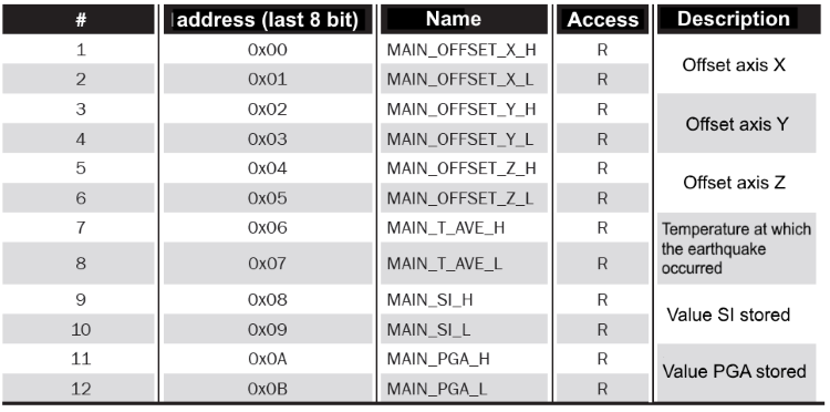
Summary description of the block of registers containing information on earthquakes. |
|
The sensor also has an internal memory in which the data relating to the last five recorded earthquakes and the five largest ones are stored, as well as, of course, all configuration settings. The D7S is composed of a three-axis accelerometer, of which only two are used during the detection of an earthquake and are selectable either by the user or automatically with respect to the inclination of the sensor. The presence of an I²C bus allows to modify the sensor settings, or to read the data related to earthquakes, by any microcontroller that is equipped with this bus and also by Arduino. The D7S sensor has a total of three function pins, of which two (INT1 and INT2) are signal pins and the third (SET) is a line used to change the operating status. Before using the sensor, the initial installation procedure must be performed, ie the sensor must detect the offsets |
|
|
|
It is good to specify that the discrimination of the collapse condition does not happen only when the sensor is switched on but whenever the sensor goes into standby; in fact, it remains possible to force control of the collapse condition by bringing the sensor into the offset acquisition mode. |
| Breakout boards |
|
The breakout boards are prototyping boards containing the already welded concerned component, whose connections are carried outside the bases on easily usable connections for pitch and termination; generally the connections are pitches with a pitch of 2.54 mm, like those of the classic integrated DIP. To facilitate those who would like to use SMD components but do not have the means or the qualities to weld it, a number of integrated sensors (including sensors, switching power supplies, battery chargers, linear amplifiers, etc.) have been identified and mounted on ready-to-use bases. These breakout boards are both an aid for those who want to have ready in a "traditional" format the best of SMD electronics, and for those who can work with SMD components - need to have these components available on prototyping boards to apply them to existing circuits and to perform tests, that is, to create prototypes that integrate the functions of the relative integrated, before realizing the final printed circuit of an apparatus. |
| Documentation and useful links |


Arduino UNO R3
The new Arduino Uno R3 (third revision). Uno now uses an ATmega16U2 to comuni..
Cod: 7300-ARDUINOUNOREV3
Price: 23.00€

Fishino UNO
Fishino UNO is an Arduino compatible development board with WiFi, microSD cards reader and RTC on bo..
Cod: 7305-FISHINOUNO
Price: 34.00€
Earthquake sensor
- Brand: Futura Group Srl
- Product Code: 7100-BREAKOUT019
- Availability: In Stock
-
Price: 52.00€
Tags: Earthquake, sensor